How Automated Layout Works on Modern Jobsites
Automated layout moves coordinated BIM/CAD information directly onto the jobsite floor.
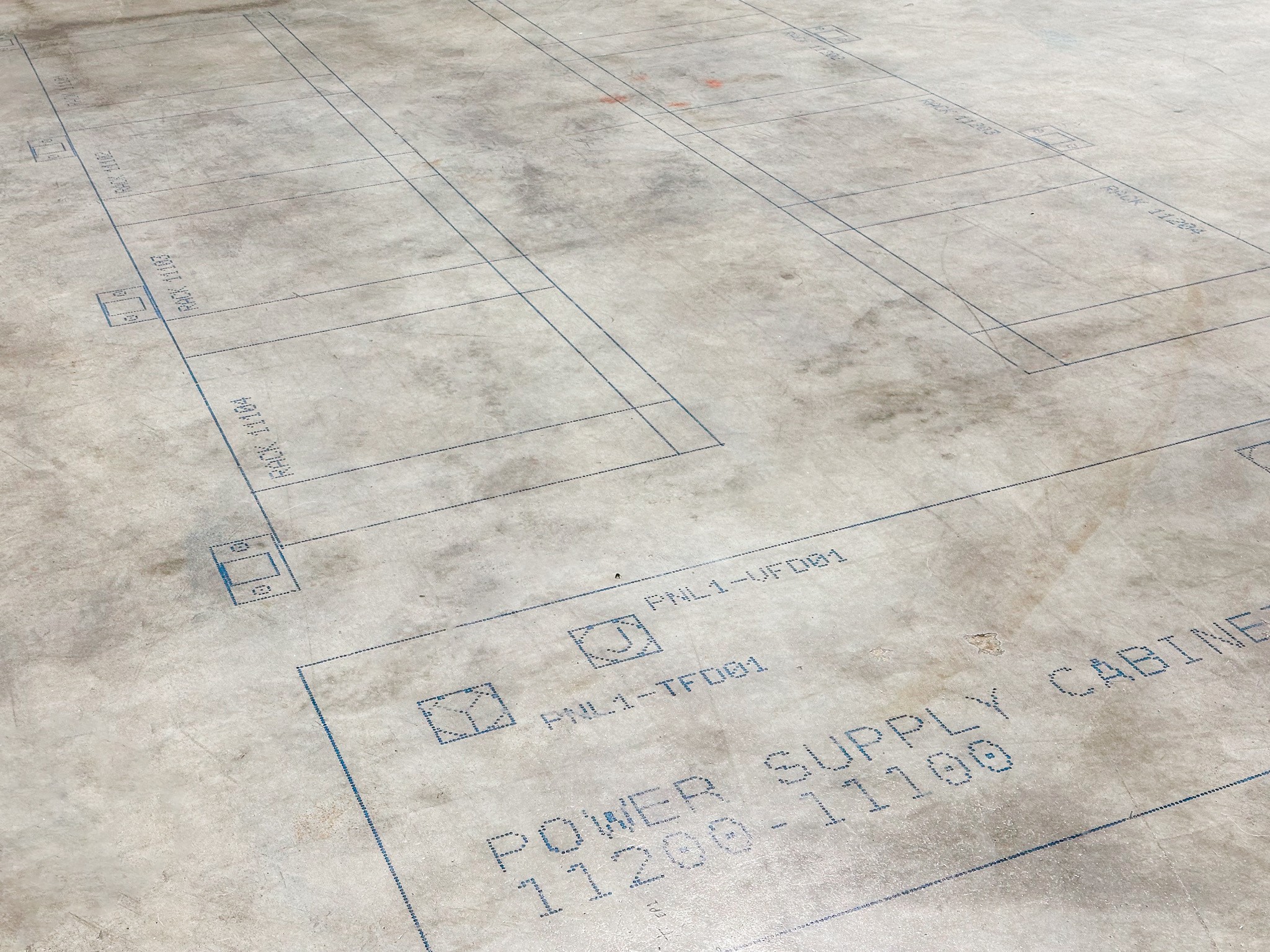
Instead of relying on manual measuring, chalk lines, trade-by-trade markup, and field interpretation, layout robots print clear, install-ready information directly on the slab or deck. That can include layout lines, equipment outlines, bolt holes, labels, symbols, elevations, and trade-specific instructions pulled from the coordinated model.
The result is a faster, more consistent handoff from design to installation. Crews are not left translating drawings in the field or second-guessing what a mark means. They can see where work needs to go, with the detail required to install accurately the first time.
On complex jobsites like data centers, automated warehouses, and industrial facilities, that matters. These projects often carry dense equipment, overlapping trades, compressed schedules, and limited room for rework. Traditional layout can become a bottleneck because every trade adds another pass, another interpretation, and another opportunity for small errors to compound.
A modern automated layout workflow typically starts with the coordinated model, identifies the features that need to be printed, verifies the site control network, and then transfers that information to the floor through continuous, high-accuracy printing. Done well, layout becomes less of a field translation exercise and more of a direct model-to-installation process.
The value is not just faster layout. It is faster installation, cleaner coordination, smoother QA/QC, reduced rework, and greater schedule certainty. Automated layout turns the slab into a shared reference point for the field, helping teams move from coordinated design to coordinated execution.
What Is a Construction Layout Robot?
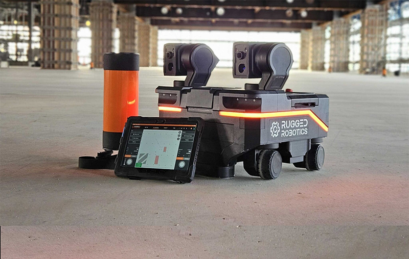
A construction layout robot is a mobile field robot that marks layout information directly onto a slab or deck using data from a coordinated BIM/CAD model.
It is purpose-built for layout. Its role is to take the information already coordinated in the model and transfer it to the floor in a way crews can read, trust, and build from.
That usually includes more than basic points and lines. Modern layout robots can print trade-specific information such as wall lines, equipment outlines, bolt locations, sleeves, embeds, symbols, labels, elevations, part IDs, and installation notes. The goal is to reduce field interpretation and give installers a clear reference at the point of work.
A typical construction layout robot includes four core components:
- A mobile base that moves across the slab or deck.
- A high-accuracy positioning system tied to the site control network. Approaches vary by platform. Some rely on robotic total stations or similar external instruments, while Rugged uses onboard localization and site references.
- A marking system that places ink, paint, or pen marks at modeled coordinates.
- A model interface that converts coordinated BIM/CAD data into executable layout instructions.
In practice, the robot becomes the connection point between virtual coordination and physical execution. The model defines what should be built. Automated layout makes that information visible, consistent, and usable in the field.
How Do Construction Layout Robots Work?
Construction layout robots work by translating coordinated BIM/CAD data into physical marks on the slab.
At a basic level, the system needs three things to work correctly: a coordinated model, a reliable jobsite reference, and a marking system that can place information accurately on the floor.
The model defines what needs to be laid out. That can include wall lines, penetrations, sleeves, anchor points, equipment outlines, fixture locations, MEP references, labels, symbols, and trade-specific instructions.
The jobsite reference ties that model to the physical building. Site control allows the robot to understand where it is on the slab relative to the project’s coordinate system. Different platforms handle this in different ways, including external instruments, site targets, onboard localization, or other reference methods.
The marking system then converts the digital layout file into readable field information. Instead of crews extending measurements manually from drawings or isolated points, the robot prints coordinated layout directly where the work will happen.
The result is a direct connection between the coordinated model and field execution. Layout becomes visible, consistent, and easier for trades to build from.
Step-by-Step: How a Layout Robot Is Used on a Jobsite
On a jobsite, automated layout is typically delivered through a simple field workflow.
1. Prepare the layout file
The layout team starts with the coordinated BIM/CAD model and identifies the information that needs to be printed. This may include architectural, structural, MEP, equipment, and trade-specific details organized into a field-ready layout file.
2. Coordinate the scope
Before printing begins, the project team confirms what needs to be laid out, where the work will happen, and which trades will use the markings. This helps avoid unnecessary information on the slab and ensures the printed layout supports installation.
3. Verify site control
The site control network is checked so the printed layout aligns with the project’s coordinate system. This step connects the digital model to the physical slab.
4. Mobilize and print
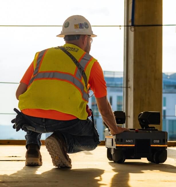
The robot is deployed on the floor, localized to the jobsite reference, and used to print the approved layout directly onto the slab. Depending on the scope, this may include one trade, multiple trades, or dense equipment layouts printed in coordinated sequence.
5. Check and hand off
Once layout is complete, the work is checked and handed off to the trades. Crews receive a clear physical reference at the point of installation instead of relying on disconnected drawings, manual measurements, or field interpretation.
The result is a slab that functions like a field-ready version of the coordinated model: visible, consistent, and ready to build from.
What Affects Construction Layout Robot Accuracy?
Construction layout robots can deliver highly accurate layout, often within 2–3 mm relative to the project’s control network. But accuracy is not created by the robot alone. It depends on the quality of the full layout workflow, from the model to the slab.
The most important variables are:
- Control network quality: Layout is only as accurate as the control it is tied to. If the site control is off, that error will carry into the printed layout.
- Slab condition: Surface roughness, moisture, dust, debris, curing state, and active site conditions can affect navigation, print quality, and mark readability.
- Model integrity: The robot prints the information it is given. If the model is incomplete, outdated, or not fully coordinated, automated layout will make those issues visible in the field.
- Positioning approach: Different platforms use different localization methods, including total stations, site targets, onboard localization, or other reference systems. The setup, stability, and suitability of that approach can affect field accuracy.
- Field execution: Experienced operators matter. Strong deployments pair autonomous layout with people who understand jobsite conditions, recognize model and control issues, and catch problems before they become layout errors.
Compared to manual methods, robotic layout reduces the small transcription and measurement errors that can compound across a large floor: misread dimensions, missed gridlines, off-center chalk lines, inconsistent markups, and trade-by-trade interpretation. The result is not just tighter layout. It is more consistent execution across the full jobsite.
Trade-Specific Use Cases for Construction Layout Robots
Construction layout robots are most valuable when the work is dense, coordinated, and schedule-sensitive. For MEP, drywall, and equipment installation, automated layout helps crews work from the same field-ready reference instead of interpreting separate drawings, measurements, and markups.
MEP
For mechanical, electrical, and plumbing teams, automated layout can print sleeves, hangers, embeds, penetrations, equipment pads, fixture locations, routing references, utility drops, and access zones directly onto the slab.
This is where coordinated layout pays back quickly. MEP work is often dense, overlapping, and highly dependent on the accuracy of other trades. When layout is printed alongside architectural, structural, and equipment information, crews can see their scope in context before installation begins. That helps reduce clashes, speed up rough-in, and make QA/QC easier in the field.
Drywall
For drywall and framing teams, automated layout can print wall lines, door openings, frame details, shaft walls, soffits, ceiling heights, header references, and room or wall identifiers in a single pass.
That level of detail reduces the back-and-forth of layout, framing, checking, and re-layout that can consume days on large or repetitive floor plates. Crews can move faster because the slab already shows where the wall goes, what it is, and how it relates to nearby penetrations, sleeves, and MEP conditions.
Equipment and automation systems
For data centers, automated warehouses, and industrial facilities, construction layout robots can print equipment outlines, baseplates, bolt holes, fiducials, charger locations, fencing, racking, workcells, conveyance, floor tape references, utility drops, and installation labels.
See how robotic layout has performed on data center projects and warehouse builds, and review real-world results in the project case studies.
Manual Layout vs. Construction Layout Robots
Manual layout is not wrong. It works on many projects and has been the industry standard for decades.
The challenge is complexity. On data centers, automated warehouses, hospitals, and industrial facilities, layout often includes thousands of details across MEP, drywall, equipment, penetrations, embeds, and access zones. As that information grows, manual layout becomes harder to keep consistent across trades, crews, and large floor plates.
Construction layout robots use coordinated BIM/CAD data to print field-ready information directly onto the slab, creating a clearer connection between the model and installation.
| Factor | Manual Layout | Construction Layout Robots |
| Speed | Multiple trade-by-trade passes that can take days. | Faster, continuous printing from coordinated layout files. |
| Accuracy | Depends on crew discipline and field measurement. | High-accuracy layout relative to verified site control, often within 2–3 mm. |
| Coordination | Trades often lay out separately and resolve issues in the field. | Multiple scopes can be printed from the coordinated model. |
| Field clarity | Crews interpret drawings, dimensions, and isolated points. | Crews see lines, labels, symbols, outlines, and notes on the slab. |
| Rework risk | Higher risk of transcription errors and inconsistent references. | Lower risk when the model, control, and scope are coordinated. |
| Labor | Skilled crews spend time measuring, marking, checking, and re-laying out. | Smaller trained team supports automated printing, freeing labor for higher-value work. |
| Repeatability | Can vary by crew, trade, shift, and site. | More consistent across floors, zones, projects, and rollouts. |
Manual layout can still be effective for simpler scopes. On dense, fast-moving projects, automated layout creates a more reliable execution layer between the model and the field.
Practical Benefits of Construction Layout Robots
Construction layout robots create value by making coordinated model information usable in the field. The biggest benefits show up in speed, consistency, and fewer installation issues.
- Reduced rework: Coordination issues are easier to catch during layout prep, before they become field conflicts during framing, rough-in, or equipment installation.
- Faster layout: Large, multi-trade layouts can be completed in a faster, more continuous workflow instead of repeated trade-by-trade passes.
- Stronger BIM-to-field connection: The slab becomes a physical extension of the coordinated model, turning VDC work into install-ready field information.
- Better trade coordination: Crews can see their scope alongside adjacent trades, equipment, penetrations, and access zones before installation begins.
- Schedule compression: Faster, clearer layout helps follow-on trades start sooner and reduces the chance that layout becomes a critical-path bottleneck.
- Clearer QA/QC: Printed layout gives teams a visible reference for checking work in the field and confirming alignment before issues compound.
- Improved repeatability: On multi-floor buildings, rollout programs, or repetitive spaces, automated layout applies the same logic consistently across every area.
- Less field interpretation: Crews spend less time translating drawings, dimensions, and isolated points, and more time installing from clear information on the slab.
When Should a Project Use a Construction Layout Robot?
A project should consider automated layout when the work is complex, repetitive, coordination-heavy, or sensitive to rework. Construction layout robots are especially useful when:
Multiple trades need to work from the same reference: MEP, drywall, equipment, and other scopes need to align in the field.
Layout repeats across floors or sites: Repetitive spaces benefit from a consistent, model-driven approach.
Small errors create expensive problems: Tight tolerances, dense equipment, sleeves, embeds, and penetrations leave little room for layout drift.
The project already uses BIM/VDC coordination: Automated layout helps turn coordinated model information into clear field markings.
Manual layout is slowing the schedule: Trade-by-trade layout, repeated checks, and re-layout can become a bottleneck for installation.
Downstream installation depends on accuracy: Reliable layout helps crews install faster, coordinate more easily, and reduce avoidable rework.
In general, the stronger the need for speed, precision, repeatability, and coordination, the stronger the case for automated layout.
Construction layout robots deliver the most value on projects where layout is large, dense, repetitive, or directly tied to schedule risk. They are especially useful for:
Large floor plates: data centers, warehouses, distribution centers, and hyperscale facilities with high volumes of layout across wide areas.
MEP-dense environments: Hospitals, labs, semiconductor fabs, and other facilities where multiple trades need to coordinate in tight spaces.
Repetitive scopes: Multi-floor buildings, phased projects, or rollout programs where the same layout logic needs to be applied consistently.
Schedule-driven projects: Jobs where layout sits on the critical path and delays can slow framing, rough-in, equipment installation, or commissioning.
Model-driven projects: Projects with a strong coordinated BIM/CAD model where the GC, VDC team, and trades want that investment to carry into the field.
Common Misconceptions About Layout Robots
“Layout robots replace field teams.”
Construction layout robots do not replace field expertise. They support field teams by taking on repetitive layout work, reducing manual measuring, and freeing crews to focus on higher-value tasks. People still need to understand site conditions, validate layout, coordinate changes, and install the work.
“Robotic layout is only for BIM-heavy projects.”
BIM/VDC workflows make automated layout more powerful, but they are not the only path. Layout robots can also work from well-prepared CAD or digital layout files. The key requirement is clean, accurate layout data.
“Robotic layout removes the need for quality control.”
Automated layout improves consistency, but QA/QC still matters. Teams still need to verify control, review layout data, confirm field conditions, and check that the right information is being printed in the right place.
“Manual layout is always cheaper.”
Manual layout may look less expensive upfront, but layout errors often show up later as rework, delays, coordination issues, and trade disruption. Automated layout should be evaluated on total project impact, not layout labor alone. See the ROI breakdown.
Frequently Asked Questions
What BIM or CAD files are needed?
A coordinated BIM model is ideal, but Rugged can also work from well-prepared CAD or digital layout files. The key is having clean layout data, clear scope definition, and current information about the features that need to be printed. Rugged helps translate that information into a field-ready layout package.
Who operates the robot on site?
With Rugged, automated layout is delivered as a full-service workflow. Rugged prepares the layout data, mobilizes the equipment and field team, verifies control, prints the approved scope, and supports handoff to the trades. Project teams get automated layout without adding a new tool, training burden, or onsite management responsibility.
Do layout robots replace surveyors or layout crews?
No. The strongest deployments pair automated layout with experienced layout professionals, field operators, survey teams, and trade partners. Robots take on repetitive marking and measuring work, while people verify control, manage quality, interpret site conditions, coordinate changes, and keep skilled crews focused on higher-value installation work.
How does automated layout support QA/QC?
Printed layout gives project teams a visible reference for checking work before installation errors compound. Teams can verify that sleeves, penetrations, wall tracks, equipment pads, bolt holes, and other features align with the coordinated model before follow-on trades proceed. That makes QA/QC faster, clearer, and easier to document.
Can layout robots be used in active or phased facilities?
Yes. Automated layout can be useful in active or phased facilities when site access is constrained and schedules are tight. The workflow should account for open work areas, changing access, safety requirements, and installation sequencing. Rugged’s field team coordinates deployment around those realities so layout supports the schedule without disrupting operations.
How should teams evaluate the ROI of automated layout?
ROI should be evaluated beyond layout labor alone. The larger impact often comes from faster installation, fewer layout-driven errors, reduced rework, smoother QA/QC, better trade coordination, and earlier access for follow-on work. The strongest business case appears when layout is tied to schedule certainty, commissioning, go-live, or portfolio-wide repeatability.
Are construction layout robots only for general contractors?
No. General contractors, specialty trades, owners, system integrators, program teams, and operations leaders can all use automated layout. The common factor is not the contract structure. It is a project or rollout where speed, precision, repeatability, and multi-trade coordination matter.
How is Rugged different from buying or renting layout equipment?
Rugged is not just layout equipment. It is a full-service automated layout partner that brings the platform, operators, model processing, deployment planning, field execution, and handoff support. That removes the friction of training staff, managing equipment, troubleshooting technology, or stretching already constrained field teams.
Conclusion: Why Construction Layout Robots Are Becoming a Field Standard
Construction layout robots are no longer a future-state idea. They are a practical jobsite tool for turning coordinated BIM/CAD data into precise, multi-trade layout on the slab.
The technology matters, but the workflow matters more. Strong results depend on clean layout data, early VDC coordination, verified site control, clear scope definition, and experienced field teams who know how to manage the handoff from model to floor.
As projects become more complex and schedules get tighter, automated layout creates a direct bridge between coordination and installation. It helps reduce field interpretation, compress layout schedules, improve trade coordination, support QA/QC, and create a clearer record of what was laid out.
Manual layout will continue to have a place, especially for simple scopes, small footprints, and field-specific adjustments. But on demanding, multi-trade projects, the real question is not whether automated layout works. It is whether the project is coordinated enough to take full advantage of it.
Ready to see what robotic layout looks like on your project?
Request an Expert Project Layout Review or explore how the workflow works end-to-end.