Quick Answer: A layout robot in construction is an automated machine that reads BIM or CAD files and prints precise layout markings, including lines, points, text, and symbols, directly onto the jobsite floor. It replaces manual chalk lines and tape measurements, often delivering sub-inch accuracy across an entire floor in hours rather than days, with a single operator managing the robot while it works.
Walk any large commercial jobsite before the trades move in and you’ll find a layout crew doing one of construction’s most labor-intensive jobs by hand: snapping chalk lines, shooting points with a total station, and systematically marking a concrete slab that may cover hundreds of thousands of square feet. Depending on the scope, that process takes days. Sometimes weeks. And when a measurement is off, even by a fraction, the rework that follows can cost far more than the layout itself.
Layout is the foundation of every trade coordination on a job. MEP crews need accurate hanger points. Drywall framers need precise wall locations. Structural embeds need to land exactly where the model says they should. When layout is slow, inaccurate, or misinterpreted, the downstream effects ripple through the entire project schedule.
Construction layout robots are changing that. By automating the translation of digital building models into precise physical markings, they’re compressing layout timelines from weeks to hours, improving accuracy beyond what manual methods can reliably achieve, and giving construction teams a faster path from design intent to field execution. Here’s exactly what they are, how they work, and what they can do for your project.
What Is a Construction Layout Robot?
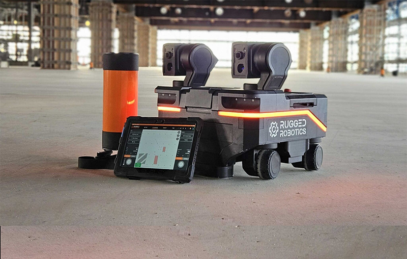
A construction layout robot is a mobile field robot that marks layout information directly onto a slab or deck using data from a coordinated BIM/CAD model.
It is purpose-built for layout. Its role is to take the information already coordinated in the model and transfer it to the floor in a way crews can read, trust, and build from.
That usually includes more than basic points and lines. Modern layout robots can print trade-specific information such as wall lines, equipment outlines, bolt locations, sleeves, embeds, symbols, labels, elevations, part IDs, and installation notes. The goal is to reduce field interpretation and give installers a clear reference at the point of work.
A typical construction layout robot includes four core components:
- A mobile base that moves across the slab or deck.
- A high-accuracy positioning system tied to the site control network. Approaches vary by platform. Some rely on robotic total stations or similar external instruments, while Rugged uses onboard localization and site references.
- A marking system that places ink, paint, or pen marks at modeled coordinates.
- A model interface that converts coordinated BIM/CAD data into executable layout instructions.
In practice, the robot becomes the connection point between virtual coordination and physical execution. The model defines what should be built. Automated layout makes that information visible, consistent, and usable in the field.
How Does a Construction Layout Robot Work?
The process slots directly into your existing project workflow and breaks down into five stages:
Step 1: Prepare the Layout File
The layout team starts with the coordinated BIM/CAD model and pulls out what needs to be printed – architectural, structural, MEP, equipment, and other trade details – into a field-ready layout file. Rugged Robotics accepts Revit (.RVT), AutoCAD (.DWG/.DXF), and CSV point exports. Clashes get resolved and trade layers organized before anything reaches the slab. Your VDC team sends the files; the layout team handles the rest – no new software or training for your in-house staff.
Step 2: Coordinate the Scope
Before printing starts, the project team confirms what gets laid out, where, and which trades will use the markings. This keeps the slab clean and makes sure the printed layout matches how the work will actually get installed.
Step 3: Verify Site Control
The site control network gets checked so the printed layout lines up with the project’s coordinate system. This is what ties the digital model to the physical slab, before the robot starts printing.
Step 4: Mobilize and Print
The robot and operator arrive on-site and check in with your superintendent or project manager, then verify position and orientation against established control points. Rugged can work off-hours or overnight to help recover time lost to delays or trade sequencing conflicts. Using a 5½-inch printhead and holonomic drive system, the robot moves across the slab and prints exactly where the model specifies – including curves, compound angles, and tight clearances around openings, without losing its position. Depending on scope, that might be one trade, several trades, or dense equipment layouts printed in sequence.
Step 5: Check and Hand Off
The operator checks output quality throughout, and the robot logs completion in real time – so you know what was printed and when. Once it’s done, crews get a physical reference at the point of installation instead of drawings, tape measures, or guesswork. The output also holds up as as-built documentation at closeout.
Benefits of Layout Robots in Construction
Speed: Hours Instead of Days
Manual layout for a dense commercial floor with multiple trade scopes can take a crew of two to four people several days or even weeks to complete. A layout robot compresses the same scope to hours. On MEP-heavy floors, where hanger density is high and coordination between trades is critical, that compression translates directly into schedule recovery, not just efficiency. Brogoitti Construction used Rugged Robotics to cut their equipment installation layout and timeline from 8 weeks to under 2 weeks, a 75% reduction, with hard dollar savings of approximately 50%.
Accuracy: Sub-Inch, Repeatable Results
Rugged’s Mark1 robot can typically deliver accuracy within 1/8 inch (approximately 2–3mm), compared to ±0.39 inches (5–10mm) for experienced manual layout crews. That may sound like a small difference, but at scale, across hundreds of hanger points, wall intersections, and structural embeds, the gap between those tolerances determines whether your trades install cleanly or spend days correcting misalignment. Accuracy is directly bounded by the quality of site control: control points should be set at ±⅛ inch or better, and ±1/16 inch for high-precision scopes like façade or dense MEP.
Labor Efficiency: One Operator, Every Trade
A traditional layout crew typically requires two to four skilled workers, plus coordination time between trades waiting on layout to proceed. One operator can manage Rugged’s full-service layout platform while the robot works, freeing the rest of your team for installation and other high-value tasks. Over the course of a large commercial project, that labor reallocation adds up to significant cost savings. Explore the full range of use cases by trade and project type to see where the labor advantage is largest.
Multi-Trade Layout in a Single Pass
One of the most operationally powerful capabilities of layout robots is the ability to print MEP, drywall, structural, and other trade layers simultaneously in a single pass. Instead of each trade sequencing separately and waiting for the floor to be clear, all trades receive their layout at once. This reduces the bottlenecks and scheduling conflicts that are endemic to traditional sequential layout, and it cuts down on the MEP-drywall mismatch that creates costly conflicts later in the project.
Reduced Rework
Construction rework is expensive. Industry estimates put rework costs at 5–15% of total project cost on typical commercial builds, and a significant share of that traces directly to layout errors: misread drawings, compounding measurement tolerances, and points that were scuffed or shifted before trades could install from them. Layout robots reduce most of these error sources at the root, since output is generated directly from the validated BIM model with minimal manual interpretation between the drawing and the slab.
Quality Control and As-Built Documentation
Throughout the printing process, the robot tracks exactly what was laid out and when. That real-time visibility supports quality control and trade coordination while the work is happening, and it also gives the team as-built documentation for project closeout, without any additional paperwork burden on the field team.
Construction Layout Robot Use Cases by Trade
Layout robots are versatile across project types and trade disciplines. The most common applications include:
- MEP
Mechanical, electrical, and plumbing crews get their layout printed straight onto the slab: hanger points, equipment pad footprints, ductwork centerlines, conduit runs, pipe sleeves, and junction box locations, all placed so installers can start without re-measuring anything.
This is where the payoff is biggest. MEP scope tends to be crowded, overlapping, and highly sensitive to how accurately the other trades were laid out. Print it next to the structural and equipment data, and crews can see conflicts before they install instead of after — fewer clashes, faster rough-in, and QA/QC that doesn’t require guesswork.
- Drywall
For framing and drywall teams, one pass covers wall centerlines, door openings, curved partitions, soffits, chase locations, header references, and finish designations.
That’s enough detail to short-circuit the usual layout-to-framing feedback loop — the repeated checking and re-marking that eats real time on big or repetitive floors. When the slab already shows exactly where a wall lands and how it sits relative to the surrounding MEP work, crews simply move faster.
- Equipment and Automation Systems
Data centers, automated warehouses, and industrial facilities need a different kind of precision: equipment outlines, baseplates, bolt patterns, fiducials, charger positions, fencing and racking lines, workcell boundaries, conveyance paths, floor tape references, and install labels.
For a full breakdown by project type and trade, see Rugged’s use cases.
Layout Robot vs. Manual Layout: How They Compare
The case for robotic layout is strongest on projects with high layout density, multiple coordinated trades, tight schedules, or hard accuracy requirements. The higher the complexity, the greater the advantage over manual methods.
| Factor | Manual Layout | Layout Robots |
| Speed | Multiple trade-by-trade passes that can take days. | Faster, continuous printing from coordinated layout files. |
| Accuracy | Depends on crew discipline and field measurement. | High-accuracy layout relative to verified site control, often within 2–3 mm. |
| Coordination | Trades often lay out separately and resolve issues in the field. | Multiple scopes can be printed from the coordinated model. |
| Field clarity | Crews interpret drawings, dimensions, and isolated points. | Crews see lines, labels, symbols, outlines, and notes on the slab. |
| Rework risk | Higher risk of transcription errors and inconsistent references. | Lower risk when the model, control, and scope are coordinated. |
| Labor | Skilled crews spend time measuring, marking, checking, and re-laying out. | Smaller trained team supports automated printing, freeing labor for higher-value work. |
| Repeatability | Can vary by crew, trade, shift, and site. | More consistent across floors, zones, projects, and rollouts. |
Frequently Asked Questions
How much does a layout robot cost?
Cost varies by platform, project size, layout density, schedule, and delivery model. Construction layout robots are typically purchased with recurring software and usage fees or leased through a monthly subscription. Rugged takes a different approach: our full-service model is priced by project scope and includes file preparation, the platform, trained operators, mobilization, and on-site execution. There is no equipment for your team to purchase, lease, store, maintain, or operate.
How accurate are construction layout robots?
Accuracy depends on both the platform and how it is deployed. Rugged’s full-service model typically delivers layout within 2–3 mm by combining model preparation, control verification, experienced operators, and field execution in one coordinated service. Self-operated platforms may achieve similar specifications, but setup, calibration, repositioning, and operator experience can introduce additional variability. In every case, final accuracy depends on a reliable control network, coordinated model data, slab conditions, and disciplined field execution.
What BIM and CAD formats do layout robots support?
Rugged Robotics accepts Revit (.RVT), AutoCAD (.DWG/.DXF), and CSV point exports. File prep, including clash review, layer organization, and output optimization, is handled by Rugged’s team, not your field crew. Your VDC team sends the files; Rugged takes it from there.
How does a layout robot differ from a robotic total station?
A robotic total station is a surveying instrument that still requires a human operator to move a prism and mark individual points one at a time. A layout robot works differently: it uses a mobile base, a positioning system, a marking system, and a model interface to print complete layouts – lines, labels, symbols, and other trade-specific detail – directly from the coordinated model, without a person moving from point to point. Rugged’s approach doesn’t require a total station at all; it uses onboard localization and site references for positioning, which eliminates the dependency on total station equipment and gives it faster, more flexible site setup. For a full overview of how Rugged’s layout process works, see the step-by-step breakdown.
Can one layout robot handle layout for multiple trades at once?
Yes. This is one of the most significant advantages of robotic layout. Rugged can print MEP, drywall, equipment, and other trade layers in coordinated sequence, reducing the need for each trade to lay out separately. This cuts down one of the most persistent sources of scheduling bottlenecks and trade conflicts on commercial projects.
What is the ROI of using a layout robot on a construction project?
ROI varies by project complexity, but the impact goes beyond layout labor savings alone – faster installation, fewer layout-driven errors, reduced rework, smoother QA/QC, and earlier access for follow-on trades all factor in. For example, Brogoitti Construction saw a significant reduction in equipment installation timeline using Rugged Robotics. Projects with high layout density, multiple coordinated trades, tight schedules, or significant rework history tend to see the highest returns.
Ready to See Robotic Layout on Your Project?
Rugged handles the entire process, from file prep to mobilization to printing, so your crew can focus on installation. Start with a pilot project and experience the difference on your next job.