


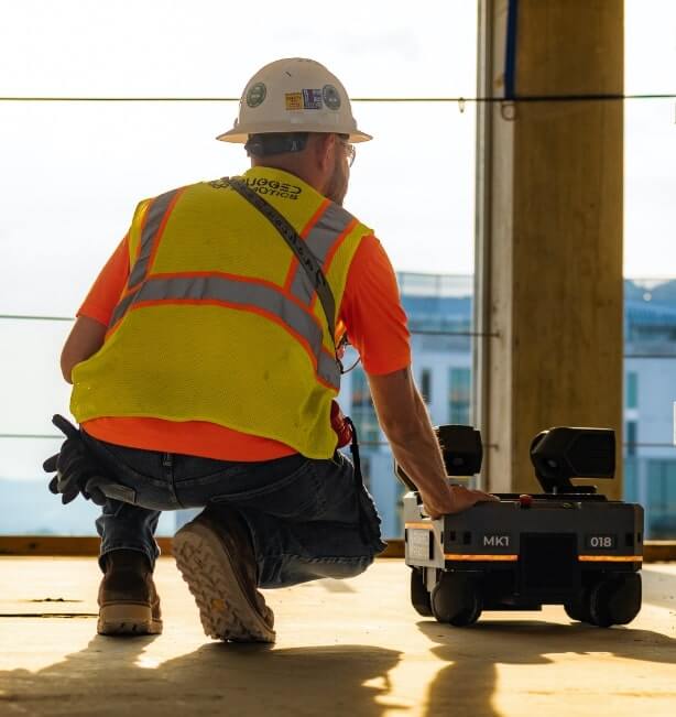
The cost of rework in construction is one of the most underestimated — and most preventable — line items on a commercial project. It rarely begins with one dramatic mistake. It usually starts with a small gap between coordinated design and field execution — a wall marked from the wrong reference, a sleeve pulled from an outdated file, two trades laying out the same area independently. The discrepancy looks minor at first. Then framing, MEP, equipment, and finishes are installed around it, and the error compounds.
By the time it becomes visible, the project is no longer correcting one mark on the slab. It is reopening installed work, moving crews out of sequence, resolving responsibility between trades, and pushing critical-path activities later. This guide breaks down the published benchmarks, the direct and indirect costs, how layout errors compound across trades, and the coordinated layout workflow that keeps them from starting.
Coordinated (or automated) layout is the practice of printing verified BIM/CAD data directly onto the slab, so field crews build from the model instead of re-measuring and re-marking it by hand — which is the throughline for preventing the rework below.
Executive Summary & Key Data
Financial impact: Published research puts direct rework at roughly 5% to 9% of total contract value on well-coordinated commercial projects, with some studies citing up to 20% on poorly coordinated builds.
Dollar loss: On the large-scale projects — roughly $500 million to $1 billion — even the conservative 5% end of that range equals $25 million to $50 million spent redoing work that should have been done once.
Primary cause: Design and documentation gaps — and the manual field transcription that compounds them — are consistently cited as the leading contributors to preventable rework.
Prevention: Coordinated, verified layout delivered within roughly 2 to 3 mm of project control is one of the most effective ways to eliminate field transcription errors before they compound across trades.
Rework costs the U.S. construction industry billions of dollars every year, and its impact scales sharply with when an error is found. A layout offset caught during digital prep takes minutes to fix in software. That same offset caught after stud framing, MEP rough-in, and drywall installation costs weeks of delay, demolished materials, and multi-trade change orders.
What Does Rework Cost in Construction?
Published industry research provides several useful benchmarks for scoping the problem:
- Construction Industry Institute (CII): Direct rework has been estimated at roughly 5% to 9% of total construction cost, with some studies citing costs as high as 20% on poorly coordinated projects.
- FMI & Autodesk (2021): “Bad data” — inaccurate, incomplete, or inconsistent project information — was linked to an estimated $88.69 billion in avoidable rework globally, roughly 14% of all rework performed in a single year.
- NIST: A widely cited 2004 NIST study linked interoperability and information-transfer gaps between design, engineering, and field systems to an estimated $15.8 billion in annual industry waste — a figure that has almost certainly grown as project complexity has increased.
These benchmarks quantify the direct hit. They do not capture the full operational cost of correcting work on an active project — and that cost climbs the later an error surfaces. Independent bodies land in the same range: the UK’s Get It Right Initiative estimates error and rework at 10% to 25% of project cost.
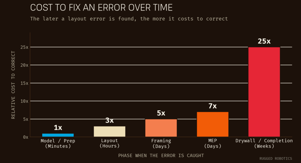 Illustrative: the relative cost of correcting an error escalates sharply with each phase it goes undetected.
Direct Costs vs. Hidden Indirect Costs
Demolished materials and re-billed labor are the most visible consequences of rework. The larger project impact usually comes from disruption:
- Schedule slippage: Installed work stops while the issue is investigated and corrected, and critical-path activities begin slipping.
- Trade stacking & congestion: Crews meant to work sequentially compete for the same space, raising coordination pressure and safety risk.
- QA/QC burden: Superintendents, project managers, and VDC teams spend field hours documenting and resolving corrections instead of advancing the job.
- Extended overhead: Rework lengthens equipment rentals, supervision, temporary facilities, and general conditions.
- Commissioning & go-live risk: On data centers, automated warehouses, and other mission-critical facilities, late field corrections compress testing and commissioning windows and push revenue-generating operations later.
The Primary Causes of Rework in Commercial Construction
Rework is often treated as a field-workmanship problem. In practice, most of it begins earlier — in the information, coordination, and references crews receive before installation starts. One industry study (PlanGrid/FMI, 2018) attributed roughly 26% of rework to poor communication and another 22% to poor or missing project information — nearly half of it traced to information gaps before installation.
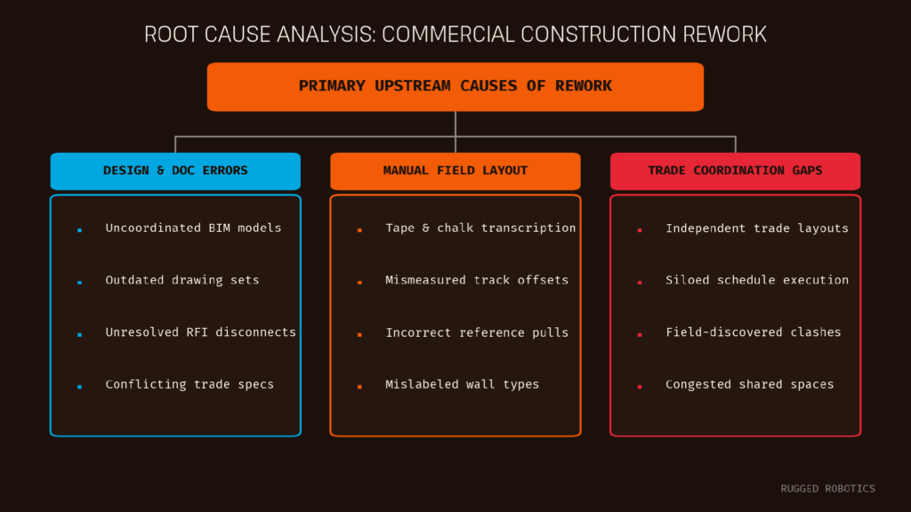 The three upstream sources that feed the majority of preventable jobsite rework.
1. Design and Documentation Errors
Incomplete drawings, unresolved clashes, outdated models, and conflicting MEP specifications are the single largest origin of rework. If the source information is wrong, even perfectly executed layout reproduces the wrong information accurately — which is why model coordination remains fundamental.
2. Manual Field Layout and Measurement Errors
Traditional layout requires crews to translate drawings into physical marks through repeated measuring, calculation, and interpretation. Every handoff creates another opportunity for variability:
- A misread offset dimension shifts a wall partition by a fraction of an inch.
- A mislabeled wall type results in a standard partition where a fire-rated assembly is required.
- A measurement pulled from an unverified reference point throws off downstream duct and pipe runs.
None of these necessarily reflects poor craftsmanship. They are inherent risks in a workflow that recreates digital information by hand in the field.
3. Trade Coordination Gaps
Complex facilities involve several trades working from different files, at different times, using different layout methods. When each subcontractor lays out independently, spatial clashes surface on the slab during installation rather than in a coordination meeting — and resolving an overhead MEP clash mid-install is far more expensive than adjusting a digital model.
How Layout Errors Compound Across the Jobsite
Layout occurs at the absolute start of field installation, which is exactly why its errors are so expensive. The references placed on the floor determine where walls, penetrations, equipment, sleeves, hanger points, and doors are installed. A single error on the slab trickles down through every trade scheduled on that floor plate.
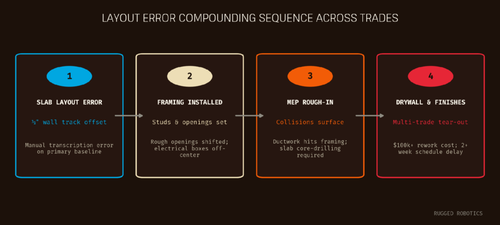 The three upstream sources that feed the majority of preventable jobsite rework.
The problem is not simply that one mark is wrong. It is that every downstream activity depends on that mark being right.
The Role of Site Control
Automated layout references the project’s site control network — the surveyed points that tie the digital BIM model to the physical building. Connected to verified control, automated layout maintains accuracy within roughly 2 to 3 mm across expansive floor plates, a precision unachievable with manual chalk lines over long distances. For a deeper look at how the hardware executes this, read Rugged’s construction layout robot guide.
How Coordinated, Automated Layout Prevents Rework
Automated layout platforms print coordinated model data directly onto the concrete slab, replacing tape measurements, hand calculations, and chalk-line transcription with a single shared physical reference. In one pass, the slab can carry:
- Full-scale wall track baselines and wall types
- MEP penetration outlines, sleeve locations, and hanger points
- Equipment pads, door swings, frames, and trade-specific labels
What Affects Layout Accuracy
Automated layout is highly accurate, but final field performance depends on several factors working together: the quality of the control network, slab and site conditions, the integrity of the coordinated model, the positioning approach the platform uses, and disciplined field execution. Automating an uncoordinated process does not fix the underlying problem — accurate layout still starts with a coordinated model and verified control.
The 5-Stage Coordinated Layout Workflow
A rework-resistant layout process follows five stages, from a coordinated model through to field handoff — the same sequence Rugged runs on every mobilization:
Stage 1 — Prepare the layout file
Freeze and federate the BIM model before layout. Combine all trade files — framing, electrical, plumbing, mechanical — into a single coordinate file from the latest agreed model, and identify exactly what needs to be printed. Layout is driven directly from Revit (.RVT), AutoCAD (.DWG/.DXF), and CSV coordinate data.
Stage 2 — Coordinate the scope
Confirm what will be laid out, where the work will happen, and which trades will use the markings before printing begins. This keeps the slab clean and keeps the printed layout matched to how the work will actually be installed.
Stage 3 — Verify site control
Verify benchmark survey points on the slab before launching hardware. Accurate layout relies directly on verified control points; this step ties the digital model to the physical structure.
Stage 4 — Mobilize and print
Print multi-trade information onto the slab in a single pass. Laying framing tracks, pipe penetrations, and electrical back-boxes simultaneously ensures every trade works from one shared physical reference.
Stage 5 — Check and hand off
Check the printed layout against the model before installation starts, then hand it off to the trades. Crews get a clear physical reference at the point of installation instead of relying on disconnected drawings or field interpretation.
Trade-by-Trade: How Coordinated Layout Reduces Rework
Layout errors do not affect all trades equally — downstream trades absorb the cumulative errors of upstream layout. Coordinated, installer-ready layout removes that exposure trade by trade.
MEP
Sleeve locations, penetration outlines, hanger points, and equipment pads printed directly on the slab keep overhead systems clash-free and eliminate the core-drilling and re-hanging that follow a shifted baseline.
Drywall & Framing
Wall centerlines, track baselines, openings, and wall-type labels — including fire-rated assemblies — reach the floor exactly as modeled, so partitions land right the first time and rough openings stay aligned for downstream trades.
General Contractor (GC)
For the GC, coordinated layout is a schedule-certainty tool, not just a trade convenience. A single coordinated reference on the slab keeps every trade building from the same source of truth, which protects the critical path, reduces change orders and trade disputes, and turns QA/QC into a fast, model-based check rather than a field investigation. Because layout is delivered as a full-service scope, superintendents and foremen and project managers get the productivity gain without taking on equipment, operators, or another tool to manage.
Equipment & Automation Systems
Baseplates, anchor locations, fiducials, and staging areas for racking, robotics, and automation infrastructure are placed to model tolerance, which is critical where equipment must tie into tightly toleranced systems.
Manual vs. RTS vs. Onboard-Localization Layout
The layout methodology a project chooses can influence its operational rework risk. Manual layout depends largely on the crew, trade, and conditions on a given day. Robotic platforms split into two categories, distinguished by how they establish position on the slab: robotic total stations (RTS) track a prism with an external optical instrument and require continuous line-of-sight, while onboard-localization platforms position themselves using internal sensors tied to site control — no external line-of-sight setup.
| Factor | Manual Layout | Robotic Total Station (RTS) | Onboard Localization |
|---|---|---|---|
| Speed | Multiple trade-by-trade passes that can take days. | Faster than manual; includes time for instrument setup and line-of-sight. | Faster, continuous printing from coordinated layout files. |
| Accuracy | Depends on crew discipline and field measurement. | High along the instrument’s line-of-sight; depends on maintaining that sightline. | High-accuracy layout relative to verified site control, often within 2–3 mm. |
| Coordination | Trades often lay out separately and resolve issues in the field. | Typically one trade or scope per setup session. | Multiple scopes can be printed from the coordinated model. |
| Field clarity | Crews interpret drawings, dimensions, and isolated points. | Crews shoot to isolated points marked on the slab. | Crews see lines, labels, symbols, outlines, and notes on the slab. |
| Rework risk | Higher risk of transcription errors and inconsistent references. | Moderate; depends on setup accuracy and maintained line-of-sight. | Lower risk when the model, control, and scope are coordinated. |
| Labor | Skilled crews spend time measuring, marking, checking, and re-laying out. | Requires a trained operator plus a prism runner per session. | Smaller trained team supports automated printing, freeing labor for higher-value work. |
| Repeatability | Can vary by crew, trade, shift, and site. | Depends on instrument setup each session. | More consistent across floors, zones, projects, and rollouts. |
Some robotic platforms, such as HP SitePrint, rely on an external robotic total station tracking a prism. Others, including Rugged Robotics, use onboard localization, which reduces reliance on external line-of-sight and per-session instrument setup on active, congested jobsites. For an in-depth breakdown of these architectures, read What Is a Layout Robot in Construction?.
How Rugged Delivers Coordinated Layout
Rugged Robotics provides automated layout as a full-service field execution partner. The project team does not purchase equipment, train operators, manage utilization, or troubleshoot another tool. Rugged handles the process end to end — from coordinated BIM/CAD information through field delivery.
Prepare
Rugged works with the VDC and project teams to identify the right files, coordinate the layout scope, and determine which lines, outlines, labels, symbols, and installation details should be printed.
Mobilize
Rugged deploys trained operators and the right robot capacity, coordinates access with the field team, and verifies layout against established control. Variable fleet deployments let capacity scale up when a project needs large areas completed inside a compressed window.
Deliver
Rugged prints detailed, coordinated layout directly on the slab, checks the completed work, and hands the area over ready for installation — fitting alongside the existing workflow instead of adding a responsibility for the superintendent, VDC team, or trade partners.
Proof: What Coordinated Layout Looks Like on Real Projects
Mission-Critical Data Center
On a hyperscale data center project, Hensel Phelps was working against an aggressive schedule in a market with a limited labor pool. Rugged deployed a full-service team across five mobilizations to lay out racking baseplates, anchor locations, wall track, HVAC passthroughs, and other architectural and engineering features across more than 250,000 square feet. More than 750 hours of physically demanding layout work were reduced and reallocated to higher-value tasks. Framing installation moved more than 15% faster because crews received installer-ready detail directly on the slab — door IDs, swings, frames, and ceiling information — and a coordinated QA/QC process let the team confirm within minutes that 100% of slab penetrations fell within the wall track.
Warehouse Automation Program
A manual process that looks manageable on a small floor plate becomes hard to control across hundreds of thousands of square feet and multiple buildings. On one warehouse automation program spanning more than 20 active facilities, Rugged developed a repeatable layout standard for robotic workcells, AMR infrastructure, charging equipment, fiducials, and staging areas. The program scaled to as many as eight simultaneous sites while working around live warehouse operations, and projects consistently finished at least 20% faster than their original schedules — without requiring warehouse downtime.
For real-world productivity and cost metrics on a commercial build, review the Brogoitti Construction case study.
Layout Automation and Skilled Labor
Construction teams already operate with limited skilled resources. The goal of automated layout is not to remove those people from the project but to redirect their time to where it adds the most value. Traditional layout involves hours of repetitive measuring, snapping lines, bending, and kneeling. Automated layout shifts that repetitive work away from field crews — freeing hours for installation, coordination, verification, and supervision while reducing physical strain and keeping output consistent throughout the workday.
Frequently Asked Questions
How much does rework cost on an average commercial construction project?
Published research commonly estimates direct rework at roughly 5% to 9% of total construction cost on well-coordinated projects, with some studies citing up to 20% on poorly coordinated builds. On the $500 million to $1 billion projects Rugged supports, 5% represents roughly $25 million to $50 million of project value.
What is the single largest cause of rework in construction?
Upstream design errors and uncoordinated BIM files are consistently cited as the leading source of rework. Manual field layout and measurement mistakes compound those upstream errors once work reaches downstream trades.
Does automated layout eliminate rework completely?
No. Automated layout cannot correct an inaccurate model, an unresolved design clash, or incorrect control. It eliminates field transcription and measurement errors by transferring coordinated information directly to the slab, and it must be paired with model coordination.
How accurate is automated layout?
Rugged typically delivers layout within approximately 2 to 3 mm relative to verified project control. Final field performance also depends on the coordinated model, the control network, site conditions, and execution.
Can automated layout support multiple trades?
Yes. A single coordinated layout package can include architectural, structural, MEP, and equipment information, reducing the inconsistencies that develop when each trade recreates layout independently.
How does onboard localization differ from total station-dependent layout?
Total station-dependent robots rely on an external optical instrument that must keep continuous line-of-sight to a prism on the robot. Onboard-localization robots navigate and position themselves using internal sensors tied to site control, eliminating external line-of-sight setups on congested jobsites.
Does the contractor need to operate the robot?
Not with Rugged’s full-service model. Rugged provides the equipment, trained operators, file preparation, mobilization, onsite execution, and field support. The project team coordinates timing and access; Rugged delivers the layout.
Key Takeaways
- Rework consumes roughly 5% to 9% of construction budgets on well-coordinated projects — and considerably more on poorly coordinated ones — which is $25 million to $50 million on the $500M–$1B projects.
- Its impact compounds: a discrepancy that costs minutes to fix before installation can consume days or weeks once multiple trades have built around it.
- Upstream coordination and manual layout transcription drive the majority of preventable jobsite rework.
- Coordinated, verified layout bridges the model to the slab within roughly 2 to 3 mm, removing manual transcription errors while keeping skilled crews in control.
Bring Rugged in before layout becomes the constraint.
Ready to eliminate layout errors on your next jobsite? Talk with our team about your next high-density floor, data hall, equipment package, or portfolio rollout — and schedule a pilot project to evaluate coordinated automated layout on your active floor plate.


